Quantcast
Channel: hardware

TUMPA

$
0
0

I was planning on “playing” with a certain device, so I wanted some adapter which allowed me to interface with the device at a low level to facilitate the information gathering phase in the hacking process. I wanted something to connect to UART signals, and a JTAG port and maybe something able to program SPI flash chips too; Marek Vasut suggested I should pick up something based on the FT2232H IC, after a round of research I settled on a TUMPA; it arrived some days ago.

Testing TUMPA under Linux

The TUMPA manual is more than OK, but some more specific info about linux can still be useful.

UART

The FT2232H has two serial channels (A and B), on the TUMPA only channel B is dedicated to UART communication, either as TTL signals or as a full RS-232 interface.

Using the TUMPA for a naked serial connection/console works fine, the linux ftdi_sio USB-serial driver can be used for that, the module can be loaded passing the vendor and product options to it:

$ sudo modprobe ftdi_sio vendor=0x0403 product=0x8a98

In this case two new device nodes show up, in my case they are /dev/ttyUSB0 and /dev/ttyUSB1, the latter corresponds to channel B.

Alternatively a patch to add direct support for TUMPA to ftdi_sio is available and will hopefully be added to linux-3.7, with this mechanism only one new device node shows up (/dev/ttyUSB0 here) which is mapped to channel B (channel A is reserved to JTAG/SPI1 on the TUMPA).

[  211.848085] usb 2-2: new high-speed USB device number 3 using ehci_hcd
[  211.996305] hub 2-0:1.0: unable to enumerate USB device on port 2
[  212.452090] usb 4-2: new full-speed USB device number 3 using ohci_hcd
[  212.652083] usb 4-2: not running at top speed; connect to a high speed hub
[  212.672078] usb 4-2: New USB device found, idVendor=0403, idProduct=8a98
[  212.672086] usb 4-2: New USB device strings: Mfr=1, Product=2, SerialNumber=3
[  212.672092] usb 4-2: Product: TIAO USB Multi-Protocol Adapter
[  212.672098] usb 4-2: Manufacturer: TIAO
[  212.672103] usb 4-2: SerialNumber: XXXXXXXX
[  212.770697] usbcore: registered new interface driver usbserial
[  212.771255] usbcore: registered new interface driver usbserial_generic
[  212.771835] USB Serial support registered for generic
[  212.771850] usbserial: USB Serial Driver core
[  212.791528] usbcore: registered new interface driver ftdi_sio
[  212.792885] USB Serial support registered for FTDI USB Serial Device
[  212.794682] usb 4-2: Ignoring serial port reserved for JTAG
[  212.794755] ftdi_sio 4-2:1.1: FTDI USB Serial Device converter detected
[  212.797208] usb 4-2: Detected FT2232H
[  212.797217] usb 4-2: Number of endpoints 2
[  212.797224] usb 4-2: Endpoint 1 MaxPacketSize 64
[  212.797229] usb 4-2: Endpoint 2 MaxPacketSize 64
[  212.797235] usb 4-2: Setting MaxPacketSize 64
[  212.808428] usb 4-2: FTDI USB Serial Device converter now attached to ttyUSB0
[  212.808477] ftdi_sio: v1.6.0:USB FTDI Serial Converters Driver

After connecting the interface to the target device, the serial console on the device can be accessed using minicom:

$ minicom -D /dev/ttyUSBX

SPI

I tested the SPI interface using a chip from an old motherboard I had lying around, it is a MX25L8005, I just needed to make the connections:

TUMPA MX25L8005 connection

TUMPA MX25L8005 connection photo

and use flashrom which already has support for both the TUMPA and the MX25L8005:

$ sudo flashrom -p ft2232_spi:type=tumpa,port=B -r flash.bin
flashrom v0.9.6.1-r1563 on Linux 3.6.0-rc5-ao2 (x86_64)
flashrom is free software, get the source code at http://www.flashrom.org

Calibrating delay loop... OK.
Found Macronix flash chip "MX25L8005" (1024 kB, SPI) on ft2232_spi.
Reading flash... done.

I2C, GPIO and bit-banging

FTDI chips are quite flexible, they can operate in a mode called Multi-Protocol Synchronous Serial Engine (MPSSE) which can be used to talk to I2C devices, or to set up some chip lines as GPIO pins, or for bit banging.

I used MPSSE via libmpsse to read data off a 24C16 EEPROM, the mapping can be derived by joining the different documents about MPSSE Basics, MPSSE Commands and TUMPA manual, a table is following for convenience:

JTAGTUMPA-jtagFT2232HMPSSEI2C
TCKpin9ADBUS0TCK/SKSCK
TDIpin5ADBUS1TDI/DOSDA
TDOpin13ADBUS2TDO/DISDA
TMSpin7ADBUS3TMS/CS
RSTpin15ADBUS4GPIOL0
nTRSTpin3ADBUS5GPIOL1WP
DBGRQpin17ADBUS6GPIOL2
RTCKpin11ADBUS7GPIOL3
DBGACKpin19ACBUS0GPIOH0
ACBUS1GPIOH1
ACBUS2GPIOH2
ACBUS3GPIOH3

And here is the final wiring to read an EEPROM via I2C:

TUMPA I2C connections

TUMPA I2C connections photo

With the GPIO mode I was also able to test a trivial circuit with a LED and a resistor and make the LED blink controlling the delay via software using libmpsse.

I don't know if MPSSE mode can be used to flash programs to PIC microcontrollers too, the PICPgm mentions a USB interface based on an FTDI chip but I didn't go deeper into the matter.

Reading the FTDI eeprom on TUMPA

The FTDI chip stores some info into an internal EEPROM, this one can be read (and flashed) using ftdi_eeprom from libftdi (NOTE: bash command line):

$ ftdi_eeprom --read-eeprom <(echo -e "vendor_id=0x0403\nproduct_id=0x8a98\nfilename=TUMPA-eeprom.bin")

The official utility to deal with the FTDI eeprom is the closed source FT_PROG.

Final words

Now that I know something more about FT2232H I think I can compare the TUMPA to simpler solutions like the basic FT2232H Mini Module:

  • On the plus side, having dedicated connectors for SPI, JTAG and TTL/RS232 on the TUMPA speeds up the connections as that avoids keeping track of the pin mapping each time.
  • On the other hand I note that the TUMPA does not make it easy to access all the FT2232H lines, which is limiting especially in MPSSE GPIO mode.

I will update the article when I get a chance to test the JTAG functionality.


Linux support for Digicom Digitune-S (vp7049, UDTT7049)

$
0
0

Support for the Digicom Digitune-S DVB-T USB stick will land in linux 3.9, the patch I sent was accepted along with other small refactorings. The adapter can also be found under these names:

A dump of the USB communication of the Windows driver is attached, it was captured using SniffUSB 2.0 and it can be made more readable using the parse-sniffusb2.pl tool from v4l-utils.

I used the dump also to figure out some details about the hardware: before writing any code I had to know what hardware components the adapter was using; the USB bridge (ULi M9206) and the frontend (MT352CG) could be seen clearly when opening the plastic case, but the tuner was protected by a metal shield and I couldn't easily find out what it was by reading the labels printed on the chip, so I tried to look at the USB communication to see if there were any clues, in particular these bits were useful:

40 23 c0 00 80 00 00 00 >>>
40 23 00 00 00 00 00 00 >>>
40 23 c1 00 80 00 00 00 >>>
c0 23 00 00 60 00 01 00 <<< 63

I thought they had something to do with some chip identification, and in fact by following the m920x driver code you can derive that this communication means more or less: “read the register at address 0x00 of the I2C device at address 0x60”; the returned value was 0x63 and by grepping through the kernel code for that value this turned out to be the same value used in the mt2060 driver for the PART_REV constant, that was enough to understand what tuner the device was using and make the jigsaw complete.

At that point adding support for the adapter was easy as all the drivers of the single components were already in the kernel, even the remote control mapping was there: separation of responsibility and modularity are good; what a surprise, eh?

The firmware was extracted from the USB dumps too, by first using parse-sniffusb2.pl:

$ v4l-utils/contrib/parse-sniffusb2.pl usbsnoop-digicom-digitune-s-dump.log_ > parsed-Digitune-S-dump.log

and then by runing m920x_parse.pl on the pre-processed log with this command line:

$ perl v4l-utils/contrib/m920x/m920x_parse.pl -i us2 -m fw < parsed-Digitune-S-dump.log
$ mv fw dvb-usb-vp7049-0.95.fw

While testing the adapter I've found out that signal reception improves when the little antenna with the magnetic base is on top of some metal object, I put mine on top of a candy tin box and I can get a few more channels, from what I read the physical principle that makes this work is the one of the ground plane of a monopole antenna.

Note to world: if you want any hardware of yours to be working under linux, just find a way to have some kernel hackers put their hands on it; the rest will come by itself.

Acer C110 pico projector with BeagleBone Black

$
0
0

I was having a hard time getting the Acer C110 USB pico projector work when connected to the BeagleBone Black, it wasn't showing up on the USB bus at all, no sign of it in the kernel messages and consequently no sign of it in lsusb. The device comes with a Y-cable so it can receive additional power, but even connecting it to an external 5V power source it still wasn't working.

I thought that the USB port on the BeagleBone had some current limit the projector was exceeding: the current supplied was not enough to power the device, and maybe the power drawn by the device was also confusing the USB host controller.

I started cutting old USB cables from broken mice in order to build a custom cable without the VCC line to the device, but then a more elegant solution came to my mind: electrical tape; I would have never thought I'd use the words “elegant” and “electrical tape” in the same sentence but here we are.

Electrical tape on VCC line of USB connector

Just isolating the VCC line on the USB connector was enough to make the device work with the BeagleBone, provided that the power was taken elsewhere using the Y-cable. I guess that ignoring the VCC line works around the “electrical stress” on the USB host controller, can anyone explain it with more technical details?

Now the device enumerates and works nicely with libam7xxx, the only trick to keep in mind in order for the device initialization to succeed is to connect first the “data” end of the USB Y-cable to the device and then connect the “power” end to the power source.

I am also attaching some pictures of the final setup.

BTW, there's also another lesson learned: don't trust color codes of cheap USB cables, always verify with a continuity test the correspondence between the cables and the pins on the connector.

Projecting the Ångström login screen
Cable setup 1
Cable setup 2

DIY wire-wrapping tool

$
0
0

Wire-wrapping is a very handy way to connect wires to PCB pins, especially in two scenarios:

  1. As an alternative to soldering, in order to be able to easily recycle the components.
  2. As an alternative to female jumper wires, in order to save some vertical space (sometimes jumper wire connectors are just too long).

A DIY wire-wrapping tool can be built from an empty ball point pen ink cartridge or from lollipop sticks, and even out of cotton swabs.

Tools made this way will work fine with solid core wires between 30 and 24 AWG like for instance those used in CAT5 cables.

Here's mine, made with a metallic pen cartridge. Last picture is an actual example of use.

metallic pen cartridge
hole in the cartridge
wire wrapping tool
wire setup
wrapping the wire
wire wrapped
wire wrapped on a trinket

JMP-rope, the hardware

$
0
0

The hardware of the first JMP-rope prototype is very simple:

  • A jump rope with large ball bearing handles, to be hacked with zip-ties. Be sure that the rope itself is not too thick, a leather one is mostly OK, but I actually used two ropes for the prototype:
    1. A DOMYOS Jump-in Skipping Rope for the handles, it has nice handles but the rope itself is a little too thick and stiff.
    2. A DOMYOS Basic Skipping Rope for the actual rope: thin and flexible.
    The two together costed less than a leather rope.
  • A micro-controller small enough to fit inside the rope handle: I used a Trinket, relying on wire wrapping to do the needed connections.
  • A small battery: I used a 150mAh lipo battery, a bigger one would have not fit into the handle. A charger for the battery is also good to have, maybe in a second prototype I'll try to stick one inside the handle too; with the current prototype the battery has to be removed in order to be recharged.
  • A LED strip, like a 30 LEDs/m Neopixel strip to tie to the rope. One meter strip will cover one side of the rope. With a beefier battery a 60 LEDs/m strip could be used. An external battery pack could also be used and kept into an arm pocket, one of those used by runners to carry cell phones or MP3 players.
  • A small slip-ring, it has to fit inside the handle; it allows the rope to spin while still keeping electrical contact between the micro-controller and the LED strip. I used a short bolt from outside the handle to hold the slip-ring in place. Ironically the bolt gives a lightsaber kind of look to the JMP-rope handle.
  • A small momentary push button.
  • Two pins and a jumper as the ON switch.
  • Zip-ties and hot glue.

I thought about using a BlinkyTape but the small battery would have not been enough for the 60 LEDs, and also the slip ring would have been necessary anyway, making the cost go higher. I did steal some code from Blinkinlabs, tho.

See the pictures below to have an idea of the building process.

If you are into hardware and want to help me realize a better prototype, get in touch. The Trinket is fine but I think more stuff could be squeezed in by using a custom board, or a Trinket daughter-board.

JMP-rope internals overview
JMP-rope handle detail
JMP-rope LED strip tied to the rope
JMP-rope programming socket
JMP-rope lit up

PS3 BD Remote Controller under raspbmc (or XBMC)

$
0
0

Here are some notes about how to use the PS3 BD Remote Controller with raspbmc (raspbmc is an XBMC distribution optimized for the Raspberry Pi). This is the software setup used in June 2014:

  • Debian Wheezy (actually raspbian)
  • linux 3.12
  • Bluez 4.99

I use one of those tiny USB Bluetooth adapters, a Mediacom M-UDBT15M.

  1. Install Bluez:
    $ sudo apt-get update
    $ sudo apt-get install bluez python-gobject-2
  2. Associate the PS3 BD Remote Controller (only needed once):
    $ hcitool scan

    then keep pressed Enter+Start on the remote for at least 7 seconds, until the BT device shows up: 00:06:F5:XX:XX:XX BD Remote Control

    Then execute these commands immediately:

    $ bluez-test-device create 00:06:F5:XX:XX:XX
    $ bluez-test-device trusted 00:06:F5:XX:XX:XX yes
    $ bluez-test-input connect 00:06:F5:XX:XX:XX

    Now the controller shows up as an input event device (/dev/input/ps3 linked to something like /dev/input/event0). The keymap can be seen by installing and running evtest.

  3. Configure lirc. This is needed because XBMC input handling is kind of weird (maybe for historical reasons), it tries too hard to differentiate between keyboards and remotes instead of just using the linux evdev API in a generic way.

    Put this in /etc/lirc/lircd.conf:

    include "/usr/share/lirc/remotes/devinput/lircd.conf.devinput"

    And this in /etc/lirc/hardware.conf

    # /etc/lirc/hardware.conf
    #
    # Arguments which will be used when launching lircd
    LIRCD_ARGS=""
    
    #Don't start lircmd even if there seems to be a good config file
    #START_LIRCMD=false
    
    #Don't start irexec, even if a good config file seems to exist.
    #START_IREXEC=false
    
    #Try to load appropriate kernel modules
    LOAD_MODULES=true
    
    # Run "lircd --driver=help" for a list of supported drivers.
    DRIVER="devinput"
    # usually /dev/lirc0 is the correct setting for systems using udev.
    DEVICE="/dev/input/ps3"
    MODULES=""
    
    # Default configuration files for your hardware if any
    LIRCD_CONF=""
    LIRCMD_CONF=""

Reboot and that's it; the default mappings in /opt/xbmc-bcm/xbmc-bin/share/xbmc/system/Lircmap.xml and /opt/xbmc-bcm/xbmc-bin/share/xbmc/system/keymaps/remote.xml are already good enough.

Remarks

Raspbmc puts its custom built version of XBMC under /opt, with custom scripts to manage updates and other tasks, why not just create Debian packages of the latest XBMC (with patches for Raspberry Pi) and set up a dedicated apt repository?

XBMC could modernize its input handling making a better use of the linux evdev API: with modern kernels more remote controls show up as input event devices, and lirc should not be needed to handle them.

Sblocco modem ADSL AGTWI su linux e senza saldature

$
0
0

Il modem ADSL2+ Wi-Fi N Technicolor, detto anche AGTWI, è fornito da Telecom Italia per i contratti residenziali; il provider non prevede il suo uso come router. Questa è evidentemente una limitazione artificiale del software fornito dal provider, dato che l'hardware è pienamente capace di funzionare come router ADSL. L'hardware è basato su quello del router Technicolor TG582n, la variante usata da Telecom viene chiamata TG582Tn.

La procedura di sblocco del modem ADSL AGTWI per permetterne l'uso come router è interessante: invece di sfruttare una vulnerabilità (o una backdoor) del software per ottenere privilegi e modificare la configurazione predefinita, si aggira completamente il problema sostituendo il bootloader con quello di un dispositivo abbastanza simile; dopo aver fatto ciò diventa possibile installare software di altri provider che permettono l'uso del dispositivo come router.

È possibile trovare il TG582n in due revisioni hardware, con relativa variante software: DANT-T con flash da 8MiB e DANT-1 con flash da 16MiB in configurazione dual-bank (cioè con la possibilità di contenere due immagini software da 8MiB, una alternativa all'altra). Il TG582Tn di Telecom Italia invece usa la variante software DANT-V.

La procedura per sostituire il bootloader DANT-V con quello DANT-T è stata proposta da roleo (necessaria la registrazione al forum) sul forum Il Punto Tecnico e ADSL, ed è stata ripresa fra gli altri da Rix94 e Bestemmie Digitali.

I documenti attualmente presenti in rete spiegano come saldare una interfaccia SPI per porta parallela alla memoria flash per modificarne il contenuto, e dicono di modificare il bootloader a mano copiando e incollando regioni di memoria da un file all'altro.

La procedura può essere semplificata e resa più robusta se mettiamo meglio a fuoco gli obiettivi:

  1. Leggere da una memoria flash che usa il protocollo SPI.
  2. Modificare un file binario sostituendo alcune sue regioni con quelle di un altro file binario.
  3. Scrivere su una memoria flash che usa il protocollo SPI.

Interfaccia seriale

Per lo sblocco del modem nessuna saldatura è strettamente necessaria, tuttavia, per avere maggiore controllo su cosa sta succedendo, si può saldare opzionalmente una striscia di pin sulla piazzola J3 e cortocircuitare le piazzole R62 e R63 per avere accesso all'interfaccia seriale:

Interfaccia seriale su TG582Tn

Per il collegamento si può usare un adattatore USB-seriale basato su chip Prolific PL-2303HX o un adattatore multi protocollo basato su chip FTDI FT2232H o simili.

Leggere la memoria flash SPI

La memoria flash nel mio caso è una Spansion S25FL129P; per accedere al suo contenuto può essere usato un qualsiasi programmatore SPI, non necessariamente uno auto-costruito per porta parallela.

Come programmatore SPI si può usare per esempio un TIAO USB Multi-Protocol Adapter seguendo questo schema:

Collegamento TUMPA-S25FL129P

NOTA: il datasheet di S25FL129P riporta che i pin HOLD# (per mettere il chip in pausa) e #W (per abilitare la protezione dalla scrittura) sono active-low quindi per disabilitarne le funzioni dovrebbero essere collegati a VCC, ma in questo caso va bene anche collegarli a GND, per questi motivi:

  • la funzione HOLD# si attiva al fronte discendente, cioè al cambio di livello logico da alto a basso, e collegando il pin a GND il livello è sempre basso, quindi non si attiva mai;
  • l'effetto di W# dipende anche da altri registri di stato del chip, in questo caso viene del tutto disabilitata la funzione di protezione (dal datasheet: SRWD: 0 = No protection, even when W#/ACC is low).

Per il collegamento si può usare un morsetto di test per chip SOIC-16 come il Pomona 5252, in questo modo nessuna saldatura è strettamente necessaria:

Collegamento TUMPA-TG582Tn

Per leggere la memoria usando il TUMPA si può usare flashrom:

sudo flashrom -p ft2232_spi:type=tumpa,port=A -Vr dump.bin

È utile conservare una copia di backup del contenuto della flash; potrà essere usata per riportare il dispositivo al suo stato originale.

Modificare il bootloader

A questo punto basterebbe scrivere il file bootloader_pn.bin fornito da roleo per avere un dispositivo DANT-T ed essere in grado di installare un firmware generico per DANT-T, ma così facendo si avrebbero gli stessi dati (chiavi, certificati, MAC address, serial number, product version) del modem da cui è stato preso quel file.

Per mantenere i dati del nostro dispositivo, si dovrà applicare una “patch” al file bootloader_pn.bin.

Il file bootloader_pn.binè composto da due regioni:

  • da 0x00000000 a 0x0001ffff c'è il bootloader; più precisamente c'è una routine di unpacking ed il binario vero e proprio del bootloader compresso con LZMA.
  • da 0x00020000 a 0x0003ffff c'è la “configurazione di fabbrica”; la regione viene anche chiamata mtdss e contiene i dati identificativi del singolo dispositivo.

Invece di copiare e incollare regioni di file binari a mano, è possibile usare dd in uno script di shell per automatizzare la procedura:

#!/bin/sh
#
# patch_dant-v_dump.sh - patch DANT-V flash dump with DANT-T bootloader
#
# Copyright (C) 2014  Antonio Ospite <ao2@ao2.it>
#
# This program is free software. It comes without any warranty, to
# the extent permitted by applicable law. You can redistribute it
# and/or modify it under the terms of the Do What The Fuck You Want
# To Public License, Version 2, as published by Sam Hocevar. See
# http://sam.zoy.org/wtfpl/COPYING for more details.

set -e

copy_region()
{
  local INPUT_FILE="$1"
  local OUTPUT_FILE="$2"

  local START_ADDRESS=$3
  local END_ADDRESS=$4

  local SIZE=$(($END_ADDRESS - $START_ADDRESS + 1))

  dd if="$INPUT_FILE" of="$OUTPUT_FILE" \
    skip=$(($START_ADDRESS)) count=$SIZE seek=$(($START_ADDRESS)) \
    conv=notrunc iflag=skip_bytes,count_bytes oflag=seek_bytes
}

erase_region()
{
  local OUTPUT_FILE="$1"
  local START_ADDRESS=$2
  local END_ADDRESS=$3

  local SIZE=$(($END_ADDRESS - $START_ADDRESS + 1))

  # Write all 0xff to $OUTPUT_FILE
  dd if=/dev/zero count=$SIZE iflag=count_bytes | \
    tr '\0''\377' | \
    dd of="$OUTPUT_FILE" seek=$(($START_ADDRESS)) conv=notrunc oflag=seek_bytes
}

DANT_V_DUMP_FILE=dump.bin
DANT_T_BOOTLOADER=bootloader_pn.bin
PATCHED_DANT_V_DUMP_FILE=dump_patched.bin

# Take the DANT-T bootloader
copy_region "$DANT_T_BOOTLOADER""$PATCHED_DANT_V_DUMP_FILE" 0x00000000 0x0001ffff

# Take the DANT-V mtdss region (the board specific data: serial number,
# certificates, mac addresses, etc.)
copy_region "$DANT_V_DUMP_FILE""$PATCHED_DANT_V_DUMP_FILE" 0x00020000 0x0003ffff

# Patch the product code and the firmware variant code, e.g.:
#   DANT-V -> WL
#   DANT-T -> WJ
# This does not appear to be strictly necessary, DANT-T firmwares will install
# even if we keep the DANT-V data here.
copy_region "$DANT_T_BOOTLOADER""$PATCHED_DANT_V_DUMP_FILE" 0x000216fc 0x00021713

# Patch the mtdss region in order to make the device look like a DANT-T,
# otherwise the client will still ask a DANT-V file (output of bootpd):
#
#   bootpd: info(6):   requested path=""  file="DANT-V"
#
# It is not enough to patch only the board name (0x00021727 0x00021728), some
# more data needs to be copied in order to prevent a failure with
# BLFLAG_INV_RI
copy_region "$DANT_T_BOOTLOADER""$PATCHED_DANT_V_DUMP_FILE" 0x00021727 0x00021730

# Erase all the rest of the flash, this will prevent a failure with:
#
#   Version BL: 1.0.5
#   Unhandled TLB
#
#   Unhandled exception
#   EPC=0x8130ff30, BadVAddr=0xc0830000, RA=8130fef8
#   ...
#
# The bootloader will still output the message BLFLAG_FLASH_FAIL (bad FVP) but
# that is OK, it will be fixed whith the firmware installation via tftp.
erase_region "$PATCHED_DANT_V_DUMP_FILE" 0x00040000 0x0ffffff

Scrivere la memoria flash SPI

Il file dump_patched.bin creato dallo script precedente può essere scritto con flashrom:

sudo flashrom -p ft2232_spi:type=tumpa,port=A -Vw patched_dump.bin

Installare un nuovo firmware

Per installare un nuovo firmware si può evitare di usare il Technicolor Home Install Wizard se si configura un server tftp.

Teclast X98 Air 3G: cheap Intel Bay Trail tablet, getting acquainted

$
0
0

I got a Teclast X98 Air 3G tablet from Aliexpress, it costed 168 € ( with free shipping) and has a high-definition screen and it's an Intel Bay Trail device; so Android, x86 architecture, 2GiB of RAM and 32 GiB of storage on EMMC. I think the product has some minor design issues:

  • the speakers are on the same side, the short side, not great when watching videos, but you want headphones or external speakers for better sound anyway;
  • when displaying content with a white background at medium brightness, the screen shows some —very light— yellowish gradient;
  • when using the leather cover the SIM slot and the MicroSD slot cannot be accessed, they are, well, covered;
  • the device does not rotate the screen automatically when booted in landscape mode, the android login screen is shown always in portrait mode at boot; this is inconvenient when booting the tablet while it's on the desk; BTW the firmware screens and the boot logos are also always shown in portrait mode, I guess that's OK for a tablet, but I would have picked a logo with some radial symmetry, or maybe drawn it at an angle, in order to alleviate the feeling of wrong orientation when booting with the device in landscape orientation;
  • the UEFI firmware informative screen is shown at boot, giving the boot experience and old PC feeling, or maybe I should say classic or familiar, I am not sure; this can be disabled in the firmware settings tho;

but beside that it's not bad considering the price, it's got HDMI output, 3G and a MicroSD slot (yeah, I'm lookin' right atch-ya, Google Nexuses...).

I eventually intend to run Debian on it, but let's take a look at the specs and do a full backup first.

Hardware and kernel support

Some info about the CPU:

ao2@localhost:~/WIP/Teclast $ adb shell cat /proc/cpuinfo | grep model\ name | uniq
model name      : Intel(R) Atom(TM) CPU  Z3736F @ 1.33GHz

On Debian unstable adb is available in the android-tools-adb package.

Here is the full dmesg log.

It's pretty easy to get it, as the device came pre-rooted:

ao2@localhost:~/WIP/Teclast $ adb root
ao2@localhost:~/WIP/Teclast $ adb shell dmesg > dmesg-Teclast_X98_Air_3G.log

UEFI firmware backup (with flashrom)

The firmware configuration menu (Aptio Setup Utility) can be accessed by pressing ESC or DEL on a USB keyboard connected to the USB OTG adapter.

The version I have reports these informations:

BIOS Vendor                    American Megatrends
Core version                    5.008
Compliancy                      UEFI 2.3; PI 1.2
Project Version	                A3G069 1.01 x64
Build Date and Time	        08/29/2014 09:41:04
...

There are newer firmware versions available on the net, so if I am going to test them it's better to save the one I have right now.

Get and compile flashrom on an x86 host:

ao2@localhost:~/WIP/Teclast $ git svn clone svn://flashrom.org/flashrom/trunk flashrom
ao2@localhost:~/WIP/Teclast $ cd flashrom
ao2@localhost:~/WIP/Teclast/flashrom $ make NEED_FTDI=no NEED_USB=no CFLAGS=-static LDFLAGS=-static

Copy it on the target device and read the firmware:

ao2@localhost:~/WIP/Teclast/flashrom $ adb push flashrom /data
ao2@localhost:~/WIP/Teclast/flashrom $ cd ..
ao2@localhost:~/WIP/Teclast $ adb root
ao2@localhost:~/WIP/Teclast $ adb shell
root@x98air3g_c6j6:/ # cd /data
root@x98air3g_c6j6:/data # ./flashrom -p internal -r Teclast_X98_Air_3G_IFWI_flashrom_dump.rom
flashrom v0.9.7-r1854 on Linux 3.10.20-g4a0098e-dirty (x86_64)
flashrom is free software, get the source code at http://www.flashrom.org

Calibrating delay loop... OK.
No DMI table found.
Found chipset "Intel Bay Trail".
This chipset is marked as untested. If you are using an up-to-date version
of flashrom *and* were (not) able to successfully update your firmware with it,
then please email a report to flashrom@flashrom.org including a verbose (-V) log.
Thank you!
Enabling flash write... OK.
Found Winbond flash chip "W25Q64.W" (8192 kB, SPI) mapped at physical address 0x00000000ff800000.
Reading flash... done.

root@x98air3g_c6j6:/data # exit
ao2@localhost:~/WIP/Teclast $ adb pull /data/Teclast_X98_Air_3G_IFWI_flashrom_dump.rom

So flashrom can read the flash memory just fine, I haven't tried to write it yet, but I think I'll do it soon. Since it's an SPI flash there is a chance that it's reasonably easy to re-program it with an external programmer in case of a brick. I haven't taken the device apart yet to see what physical package the flash chip uses.

EMMC backup

The EMMC contains a GPT, the available partitions can be listed following the approach in this post, we get this:

unit :  sectors
/dev/mmcblk0p1   :  start    =  40,       size  =  131072,    Id=XX
/dev/mmcblk0p2   :  start    =  131112,   size  =  131072,    Id=XX
/dev/mmcblk0p3   :  start    =  262184,   size  =  32768,     Id=XX
/dev/mmcblk0p4   :  start    =  294952,   size  =  32768,     Id=XX
/dev/mmcblk0p5   :  start    =  327720,   size  =  32768,     Id=XX
/dev/mmcblk0p6   :  start    =  360488,   size  =  32768,     Id=XX
/dev/mmcblk0p7   :  start    =  393256,   size  =  131072,    Id=XX
/dev/mmcblk0p8   :  start    =  524328,   size  =  65536,     Id=XX
/dev/mmcblk0p9   :  start    =  589864,   size  =  32768,     Id=XX
/dev/mmcblk0p10  :  start    =  622632,   size  =  32768,     Id=XX
/dev/mmcblk0p11  :  start    =  655400,   size  =  32768,     Id=XX
/dev/mmcblk0p12  :  start    =  688168,   size  =  2097152,   Id=XX
/dev/mmcblk0p13  :  start    =  2785320,  size  =  65536,     Id=XX
/dev/mmcblk0p14  :  start    =  2850856,  size  =  2097152,   Id=XX
/dev/mmcblk0p15  :  start    =  4948008,  size  =  56115160,  Id=XX

And the corresponding partition labels are:

ao2@localhost:~/WIP/Teclast $  adb shell 'ls -l /dev/block/platform/intel/by-label/' | sort -t '>' -k 2.21n | column -t
lrwxrwxrwx  root  root  2014-11-20  13:38  ESP         ->  /dev/block/mmcblk0p1
lrwxrwxrwx  root  root  2014-11-20  13:38  reserved    ->  /dev/block/mmcblk0p2
lrwxrwxrwx  root  root  2014-11-20  13:38  boot        ->  /dev/block/mmcblk0p3
lrwxrwxrwx  root  root  2014-11-20  13:38  recovery    ->  /dev/block/mmcblk0p4
lrwxrwxrwx  root  root  2014-11-20  13:38  fastboot    ->  /dev/block/mmcblk0p5
lrwxrwxrwx  root  root  2014-11-20  13:38  reserved_1  ->  /dev/block/mmcblk0p6
lrwxrwxrwx  root  root  2014-11-20  13:38  test        ->  /dev/block/mmcblk0p7
lrwxrwxrwx  root  root  2014-11-20  13:38  panic       ->  /dev/block/mmcblk0p8
lrwxrwxrwx  root  root  2014-11-20  13:38  factory     ->  /dev/block/mmcblk0p9
lrwxrwxrwx  root  root  2014-11-20  13:38  misc        ->  /dev/block/mmcblk0p10
lrwxrwxrwx  root  root  2014-11-20  13:38  config      ->  /dev/block/mmcblk0p11
lrwxrwxrwx  root  root  2014-11-20  13:38  cache       ->  /dev/block/mmcblk0p12
lrwxrwxrwx  root  root  2014-11-20  13:38  logs        ->  /dev/block/mmcblk0p13
lrwxrwxrwx  root  root  2014-11-20  13:38  system      ->  /dev/block/mmcblk0p14
lrwxrwxrwx  root  root  2014-11-20  13:38  data        ->  /dev/block/mmcblk0p15

I didn't have an empty MicroSD card handy, so I used an external hard drive connected to the USB OTG adapter to strore the backups, I had to use adb via TCP/IP:

ao2@localhost:~/WIP/Teclast $ adb tcpip
ao2@localhost:~/WIP/Teclast $ adb connect 192.168.0.99
ao2@localhost:~/WIP/Teclast $ adb root
ao2@localhost:~/WIP/Teclast $ adb shell

And I ran this script:

#!/system/bin/sh

# The data partition is more than 20GiB, let's skip it.
find /dev/block/platform/intel/by-label -type l | grep -v '/data$' |
while read partition;
do
  OUTPUT_FILE="/storage/usbcard1/$(basename "$partition").img"

  echo "Dumping '$partition' to '$OUTPUT_FILE'"
  dd if="$partition" of="$OUTPUT_FILE"
done

First quick inspection

There are some Android bootimgs (boot, fastboot, recovery) which can be modified with these Bootimg-scripts, I noticed that the kernel is compiled for a 32-bit architecture.

Some ext4 filesystems (cache, config, factory, logs, system).

Some raw data partitions (misc, panic, reserved_1, reserved, test).

The ESP partition is the UEFI boot partition (EFI System Partition), it's a FAT32 filesystem and can be loop-mounted with no problems.

A quick analysis with binwalk shows that this partition contains some 800x1000 bitmaps:

ao2@localhost:~/WIP/Teclast $ binwalk ESP.img

DECIMAL       HEXADECIMAL     DESCRIPTION
--------------------------------------------------------------------------------
1051648       0x100C00        Microsoft portable executable
1149888       0x118BC0        PC bitmap, Windows 3.x format, 800 x 1000 x 24
2465927       0x25A087        LZMA compressed data, properties: 0x5D, dictionary size: 65536 bytes, missing uncompressed size
3620864       0x374000        Microsoft portable executable
3676128       0x3817E0        PC bitmap, Windows 3.x format, 800 x 1000 x 24
4992167       0x4C2CA7        LZMA compressed data, properties: 0x5D, dictionary size: 65536 bytes, missing uncompressed size
6100480       0x5D1600        Microsoft portable executable
6198720       0x5E95C0        PC bitmap, Windows 3.x format, 800 x 1000 x 24
7514759       0x72AA87        LZMA compressed data, properties: 0x5D, dictionary size: 65536 bytes, missing uncompressed size

The pictures can be spotted with a really rough approach using rawtoppm from netpbm:

  ao2@localhost:~/WIP/Teclast $ rawtoppm -bgr 800 $(($(stat -c "%s" ESP.img) / 3 / 800)) ESP.img > ESP.ppm

It turns out that all the three pictures are equal: it's the logo shown at boot right after the UEFI firmware screen.

The logo is contained once in each of the EFI binaries:

ao2@localhost:~/WIP/Teclast $ mkdir ESP
ao2@localhost:~/WIP/Teclast $ sudo mount -o loop ESP.img ESP/
ao2@localhost:~/WIP/Teclast $ find ESP/
ESP/
ESP/EFI
ESP/EFI/Intel
ESP/EFI/Intel/Data
ESP/EFI/Intel/efilinux.efi
ESP/EFI/Intel/warmdump.efi
ESP/EFI/BOOT
ESP/EFI/BOOT/bootx64.efi
ao2@localhost:~/WIP/Teclast $ binwalk ESP/EFI/BOOT/bootx64.efi

DECIMAL       HEXADECIMAL     DESCRIPTION
--------------------------------------------------------------------------------
0             0x0             Microsoft portable executable
98240         0x17FC0         PC bitmap, Windows 3.x format, 800 x 1000 x 24
1414279       0x159487        LZMA compressed data, properties: 0x5D, dictionary size: 65536 bytes, missing uncompressed size

ao2@localhost:~/WIP/Teclast $ dd if=ESP/EFI/BOOT/bootx64.efi of=boot_logo.bmp skip=$((0x0017fc0)) count=$((800 * 1000 * 3 + 0x36)) iflag=count_bytes,skip_bytes
ao2@localhost:~/WIP/Teclast $ sudo umount ESP

firmware splash logo

I guess the logo can be pretty easily replaced with a custom one, but I haven't done that yet.

Maybe the EFI binaries just display the logo and then boot an Android boot image from the right partition, depending on the boot option.

The tablet has three boot options:

  1. normal boot (just quick press the power button);
  2. DROIDBOOT PROVISION OS (quick press the power button and keep pressed for a while the volume-down key);
  3. DnX mode, accepting fastboot commands (quick press the power button and keep pressed both volume keys for a while);

and there are three efi binaries, are these things connected?

I need to learn more about how this UEFI thing works in order to confirm that.

Just to conclude the boot-logos-analysis™, the device shows three logos during the boot sequence:

  1. the generic Teclast t-pad logo mentioned before;
  2. an animated logo referring the X98 Air 3G device, it's in Chinese but it's pretty straightforward to see that, even with zero knowledge of the language;
  3. an Intel-Inside logo.

The last two logos are boot animations, fired up one after the other by the bootanim service invoked by the init.rc file that is on the boot partition; the animation data is taken from the system partition, it's in the media/bootanimation.zip file: just PNGs, one per frame.

Pictures attached below.

So after some hours of looking I found that it'd be super easy to customize the root filesystem and even all the logos of the boot sequence; however what I really want to do is to load a custom kernel, but that's meat for another day.

boot logo 1
boot logo 2

Teclast X98 Air 3G: unbricking a Bay Trail tablet

$
0
0

While I was trying to boot a vanilla linux kernel on the Teclast X98 Air 3G I messed up a bit with the UEFI firmware settings: the battery was not recognized anymore, the tablet was rebooting right after showing the UEFI firmware boot screen, and USB-host was not working either; so no keyboard for accessing the firmware menu to restore the default settings, and no ADB for running flashrom or the Intel FPT to reflash the firmware with. I decided to open the tablet and try to reprogram the flash chip In-System. In order to open the tablet without damaging it I started from the top of the device like shown in the video, and used something like these plastic opening tools.

The SPI flash chip used for the firmware is a Winbond W25Q64FW in a SOIC-8 package, I first tried to reflash it with a TUMPA, and then with a Beaglebone Black, but I failed, and I even managed to brick the device: the boot screen was not even displayed anymore.

Guess why... it was because I was trying to flash at 3.3V while the chip is supposed to work at 1.8V.

These are the FAILS which tech you a lesson the hard way:

Read the datasheet cover to cover (and maybe even understand it).

The indication about 1.8V was on the very first page...

OK, so I had a bricked device, how would I unbrick it?

There were several scenarios ahead:

  1. The flash chip was just erased, not damaged. Try to flash the chip at 1.8V.
  2. The flash chip was damaged. Unsolder it with a cheap Hot Air station (which I got anyway), and replace the chip with a new one found on AliExpress.
    Goto 1.
  3. Operating at 3.3V damaged some other components. Get another tablet and use this one for spare parts.

Luckily 1 was the case.

In order to flash at 1.8V I used this Logic Level Converter board from Sparkfun, and attached it to the BeagleBone Black like shown in the pictures below, I followed the indications from How to Access Chips Over the SPI on BeagleBone Black; the BBB kindly supplies 1.8V at pin 32 on the P9 header, so I used that as a reference for the lower voltage for the level converter.

The software side was pretty easy as I had flashrom already working on the BBB, and I had a backup of the flash contents:

root@arm:~/flashrom# echo BB-SPIDEV0 > /sys/devices/bone_capemgr.*/slots
root@arm:~/flashrom# ./flashrom -V -p linux_spi:dev=/dev/spidev1.0 -w ../Teclast_X98_Air_3G_IFWI_flashrom_dump.rom

And the tablet was working again.

Now back to try running vanilla kernels on it.

UPDATE:
Cosimo Orlando published an article about Unbricking a Teclast X98 BIOS with Bus Pirate 4 and Flashrom.

Teclast X98 Air 3G, internals
Teclast X98 Air 3G, mainboard
ISP with a logic level converter, top
ISP with a logic level converter, angle

Linux KMS driver for Acer C120

$
0
0

Hans de Goede informs me that he has been working on gm12u320-kms: a new linux kernel driver for the Acer C120 mini projector, and possibly other devices based on the Grain Media GM12U320 USB3 bridge chip. Hans' driver exposes the projector as a KMS device and has been based on Viacheslav Nurmekhamitov's famebuffer driver.

The most interesting feature of this new driver is the support for PRIME: a cross-device buffer sharing mechanism provided by the linux DRM subsystem.

These USB displays/projectors are usually rather dumb, they just display frames passed to them in a given format, without any hardware acceleration; so PRIME is really useful for them, it allows the rendering to be performed by another (hardware accelerated) device, using the projector just for the final copy to the "screen".

Before anyone asks, this driver does not work with am7xxx devices.

Little hacks for a GoPro Hero 3 White

$
0
0

Someone came to me with a broken GoPro Hero 3 White which wasn't turning on anymore, asking if there was a cheap way to fix it.

After tearing it down, a quick inspection revealed that the two flat-flex cables (the Shutter button one and the Power/Mode+LCD one) were both damaged, so neither the buttons or the LCD were working.

However, making contacts on the PCB traces of the Power button resulted in some reaction from the camera, so I knew there was still a chance. Replacing the cables with spare parts could have been an option except that the receptacle for the Power button flat-flex was busted too. and I am not that great at micro-soldering; so I looked for an easier way out.

GoPro cameras have the so called “Herobus” interface and looking at the connector pinout for a similar model I saw that the Power button (PWRBTN) is exposed at pin 19, so an external button can be added to turn the camera on. I ended up buying a cheap compatible connector to experiment with.

I soldered a momentary button to a little piece of perf-board held into the strain-relief slot, and it works robustly enough.

Hero Bus External Power Button wiring

NOTE: do not apply too much solder to the pins of the connector, or you might risk to bridge them in places hard to reach. That happened to me and I lost quite some time struggling with flux and solder wick to get rid of the bridge.

In the picture below you can see the final result; it's an ugly contraption, but, hey, it works.

Hero Bus External Power Button

Debouncing the button is not strictly needed to power on the camera because a 1-second long press is required.

The external connector solves the problem of the busted Power button, however the Shutter button still has to be pressed somehow to be able to control the camera functions.

It turns out that, instead of buying the replacement for the flat-flex cable, a software solution can be used for that.

The hack is sometimes called “Super One-Button mode”, and it consists in putting a script named autoexec.ash in the MicroSD card: this script can contain commands to control the camera and it will be executed automatically when the camera boots. The ash extension of the file derives from the name of the command line interpreter Ambarella shell, which comes after the hardware platform used for the device, like reported in this DefConf presentation.

The camera I had was a GoPro Hero 3 White and unfortunately there were only very few basic scripts on-line for this model.

So here are some more examples I came up with.

Dump help text

The Ambarella shell supports output redirection, so the output of commands can be saved to a file for later inspection.

This script can be used to list the supported commands:

help > d:\help.txt

And from there, a script to dump the help text of various commands can be written:

bp > d:\bp.txt
config > d:\config.txt
cpu > d:\cpu.txt
date > d:\date.txt
dmesg > d:\dmesg_help.txt
dmesg rtos -100 > d:\dmesg_rtos.txt
dmesg dsp -100 > d:\dmesg_dsp.txt
eeprom > d:\eeprom_help.txt
net > d:\net_help.txt
net info > d:\net_info.txt
net status > d:\net_status.txt
poweroff > d:\poweroff_help.txt
t app curapp > d:\t_app_curapp_help.txt
t app curapp status > d:\t_app_curapp_status.txt
t app > d:\t_app_help.txt
t app key > d:\t_app_key_help.txt
t app linux_usb > d:\t_app_linux_usb_help.txt
t app msg > d:\t_app_msg_help.txt
t app tcmd > d:\t_app_tcmd.txt
t app test > d:\t_app_test_help.txt
t cal > d:\t_cal_help.txt
t disp > d:\t_disp_help.txt
t > d:\t_help.txt
t iavinfo > d:\t_iavinfo_help.txt
t k20 > d:\t_k20_help.txt
t uart > d:\t_uart_help.txt
ver > d:\ver.txt
wifi > d:\wifi_help.txt
sleep 1
poweroff yes

Enable the serial console via USB

Use this script:

sleep 4
t app test usb_rs232 1
sleep 2
t app key mode

Then:

  1. Power on the GoPro without connecting the USB cable.
  2. Wait 6 seconds and only then connect the USB cable.
  3. Open the new USB serial device (e.g. with minicom or screen).

The last command t app key mode seems to be needed to prevent the camera from cutting the serial connection.

Take a picture and then turn off the camera

This is done by changing the mode from Video to Picture, then pressing the record key (which corresponds to the physical Shutter button), and then shutting down:

sleep 2
t app key mode
sleep 1
t app key record
sleep 2
t app key power

The script assumes that Video mode is the default mode when the camera powers on.

Turn Wifi On

On the GoPro Hero3 White there is no easy way to press the Wifi button via software using the t app key command.

Presumably that could be done with the t gpio command but I didn't know what the GPIO pin number was, so I looked for an alternative way.

Using the t app key command it is possible to navigate the user menu.

The navigation steps can be figured out from the manual:

And/or by observing the steps on a fully functional camera, like here or here

To enable Wifi in App Mode the navigation is like the following:

  • press the mode button 4 times to get to the 'Settings' menu;
  • press the record button to enter the sub-menu;
  • press the mode button 6 times to get to the 'Wireless Controls' menu;
  • press the record button to enter the sub-menu;
  • press the record button again to enter the wireless mode sub-menu;
  • press the mode button 2 times to get to the 'GoPro App' mode;
  • press the record button to enable Wifi.

This results in the following script:

sleep 4
t app key mode
sleep 1
t app key mode
sleep 1
t app key mode
sleep 1
t app key mode
sleep 1
t app key record
sleep 1
t app key mode
sleep 1
t app key mode
sleep 1
t app key mode
sleep 1
t app key mode
sleep 1
t app key mode
sleep 1
t app key mode
sleep 1
t app key record
sleep 1
t app key record
sleep 1
t app key mode
sleep 1
t app key mode
sleep 1
t app key record
sleep 3
rm d:\autoexec.ash
sleep 1

Note that enabling WiFi seems to reduce the USB functionality, for instance it is not possible to enter the USB RS232 mode anymore, and the USB Mass storage mode gets disabled too.

A similar script can be used to disable the Wifi if needed.

Conclusions and final notes

A software solution to an hardware problem is not always the best one, but in this case it surely was the cheapest one.

In case a script produced some weird side-effect a manual firmware update can be performed to try to reset all the camera default status; this requires a charged battery. The upgrade process can take up to 5 minutes, so don't panic too early if the GoPro does not seem to be active for a while.

My collections of autoexec.ash scripts for the GoPro Hero 3 White has been merged in KonradIT/autoexechack.

Low-cost and precise rotary encoder with magnetic spheres

$
0
0

You know what they say that constraints drive creativity, I think this post is just another little example of that.

Usually I do not put time constraints to my hobby projects, but I make sure to have some other kind of constraints, like keeping the cost low and trying to reuse stuff that I already have.

In this case I needed a way to measure the angle and speed of a rotating object for some of my projects, and I wanted a rotary encoder that was inexpensive, but precise enough to work at very low speeds. I ruled out optical encoders (I could have reused a mouse) because there could have been noise issues in the final project, so I decided to go magnetic.

I purchased a couple of Hall effect sensors but I had no idea of how I was going to use them.

Later I realized that the US1881 sensors I bought were bipolar latching sensors (check out the Hallbook for a nice reference of magnetic sensing), meaning that their state would persist when the magnet was out of reach.

These kind of sensors are not designed to be used with the magnetic pole facing the sensor, in a reed-switch fashion, they require alternating magnetic poles to switch states; most of the time these Hall effect sensors are used with ring magnets.

I didn't want to buy a different sensor (unipolar ones may work better with sparse magnets) or a dedicated ring magnet, so I started to think about how to build a ring magnet from what I had lying around.

One way to build a ring magnet is to place small magnets with alternating poles in a circular arrangement, like proposed in Custom 3D Printed Magnetic Encoder Disks for Robotics Projects by Erich Styger.

However I don't have a 3D printer, nor such small magnets, but I had around a Tetramag: a toy made of magnetic spheres.

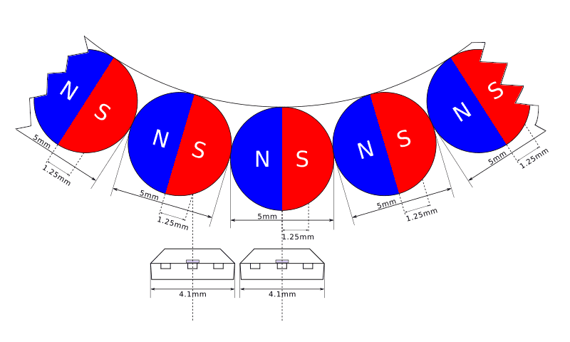
The Tetramag spheres have a diameter of 5mm, that means that a pole covers about 2.5mm (pole pitch) and that the "element pitch" (the distance between the two sensing elements) should be of about 1.25mm.

Check out the section about quadrature in the Hall-Effect IC Applications Guide from Allegro Microsystems for more info.

In practice, though, the two sensing elements do not necessarily need to be adjacent and cover the same magnet, it's enough that they are in a position which results in a quadrature signal: with the two channels being out of phase of about 90 degrees, like shown in the following picture:

Tetramag ring magnet - element pitch

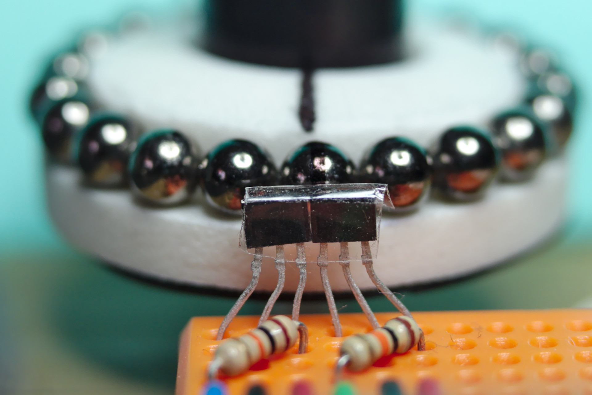
And here is a photo of the sensors position in real-life:

Hall effect sensors position

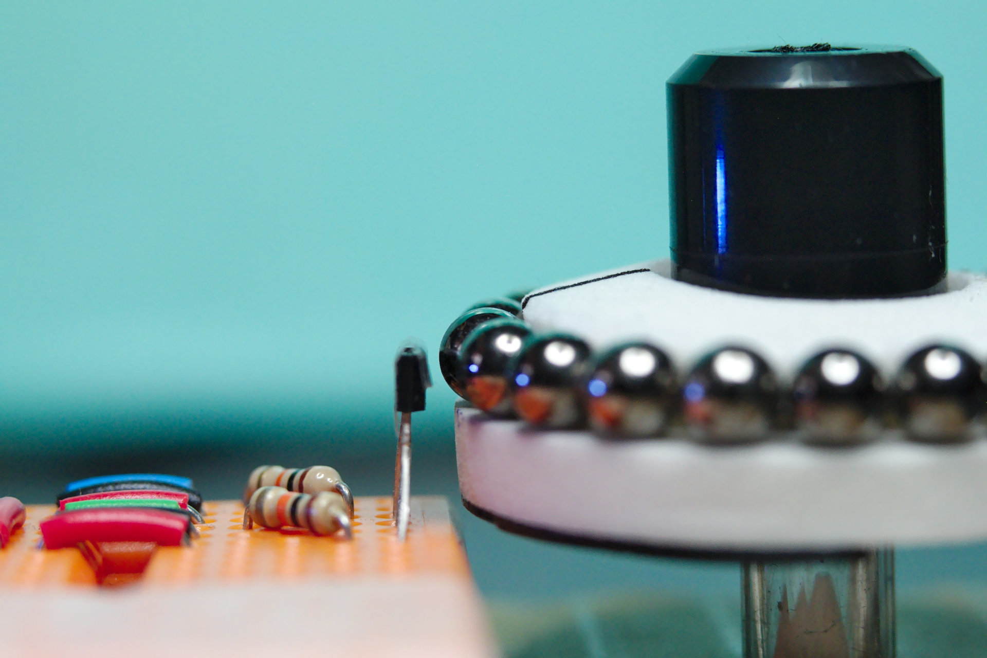
In my demo setup, a piece of a pen was used as the spindle and pieces from a CD stack case are reused for the knob of the encoder:

Rotary encoder demo setup

The result is a low-cost rotary encoder, with a precision depending on the number of spheres used to build the ring.

Look at the demo built with 21 spheres:

In this case the encoder has 21 x 4 = 84 pulses per revolution (it's a 2 channels quadrature encoder) and can measure angles down to 360 ÷ 84 = 4.29 degrees.

The code of the experiment can be found at git.ao2.it/experiments/Hall_effect_rotary_encoder.git

And now that I know more about Hall effect sensing I can decide whether a better sensor can be used for my next project: it may actually make sense to use a single dual sensor instead of two discrete sensors.

But you don't know until you know, right?

Linux Device-Tree and gpio-keys driver on BeagleBone Black

$
0
0

I had to wire up a simple navigation keypad to a BeagleBone Black for a prototype, and I used the gpio-keys driver configured via a device tree overlay. I looked for some free GPIO pins so that the keypad could be hooked up with minimal changes to the BeagleBone Black default configuration.

I am posting some details in case anyone (future-self included) needed to do the same.

Here is a table of the pins and the related keys.

Header PinFunction
P8_07Up
P8_08Left
P8_09Right
P8_10Down
P8_26Enter
P9_15Esc

I did not use P8_11 and P8_12 because they can be configured in eQEP mode and I intended to use them for a rotary encoder.

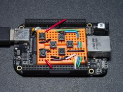
Here is a picture of how the keypad can be hooked up using a breadboard.

Navigation keypad with BeagleBone Black

And a quick video to show the functionality:

The devicetree overlay can be found at git.ao2.it/experiments/bbb-gpio-keypad.git/ and can be built and installed by running make && sudo make install, after getting the needed include files as explained in the Makefile.

Nowadays, devicetree overlays on the BeagleBone Black have to be set via the bootloader by changing the file /boot/uEnv.txt, in this case the following change was enough:

--- /boot/uEnv.txt.orig	2018-07-13 13:28:12.837315343 +0000
+++ /boot/uEnv.txt	2018-07-13 13:27:59.525770867 +0000
@@ -11,7 +11,7 @@ uname_r=4.9.105-ti-r112
 enable_uboot_overlays=1
 ###
 ###Overide capes with eeprom
-#uboot_overlay_addr0=/lib/firmware/<file0>.dtbo
+uboot_overlay_addr0=/lib/firmware/bbb-gpio-keypad-00A0.dtbo
 #uboot_overlay_addr1=/lib/firmware/<file1>.dtbo
 #uboot_overlay_addr2=/lib/firmware/<file2>.dtbo
 #uboot_overlay_addr3=/lib/firmware/<file3>.dtbo

Cyclabile, a labile bike lane

$
0
0

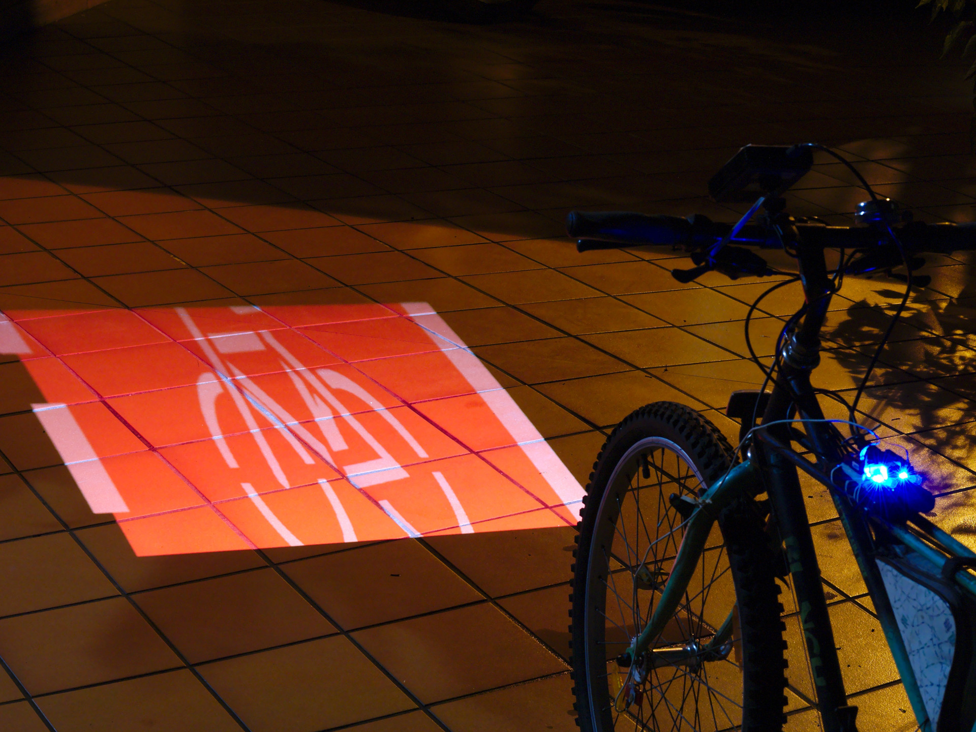
Cyclabile is an experiment about showing a moving bike lane on the road: the image moves according to the bike movement, producing the effect of riding on an actual bike lane, even when there isn't one.

The effectiveness of projecting an image on the paving instead of using a traditional light can be argued, of course.

For now the project purpose is more about having some fun and making a statement (there should be more bike lanes) rather than building an actual usable product. The prototype has been developed with a BeagleBone Black and a USB projector supported by libam7xxx because I already had those around, however if I were to start from scratch I would use a Raspberry Pi and a HDMI pico-projector, which would make the software side more flexible (graphics acceleration, no need for display-dependent code), or even a wireless projector and a BLE sensor connected to a smartphone.

The source code of the prototype is at https://git.ao2.it/experiments/cyclabile.git/.

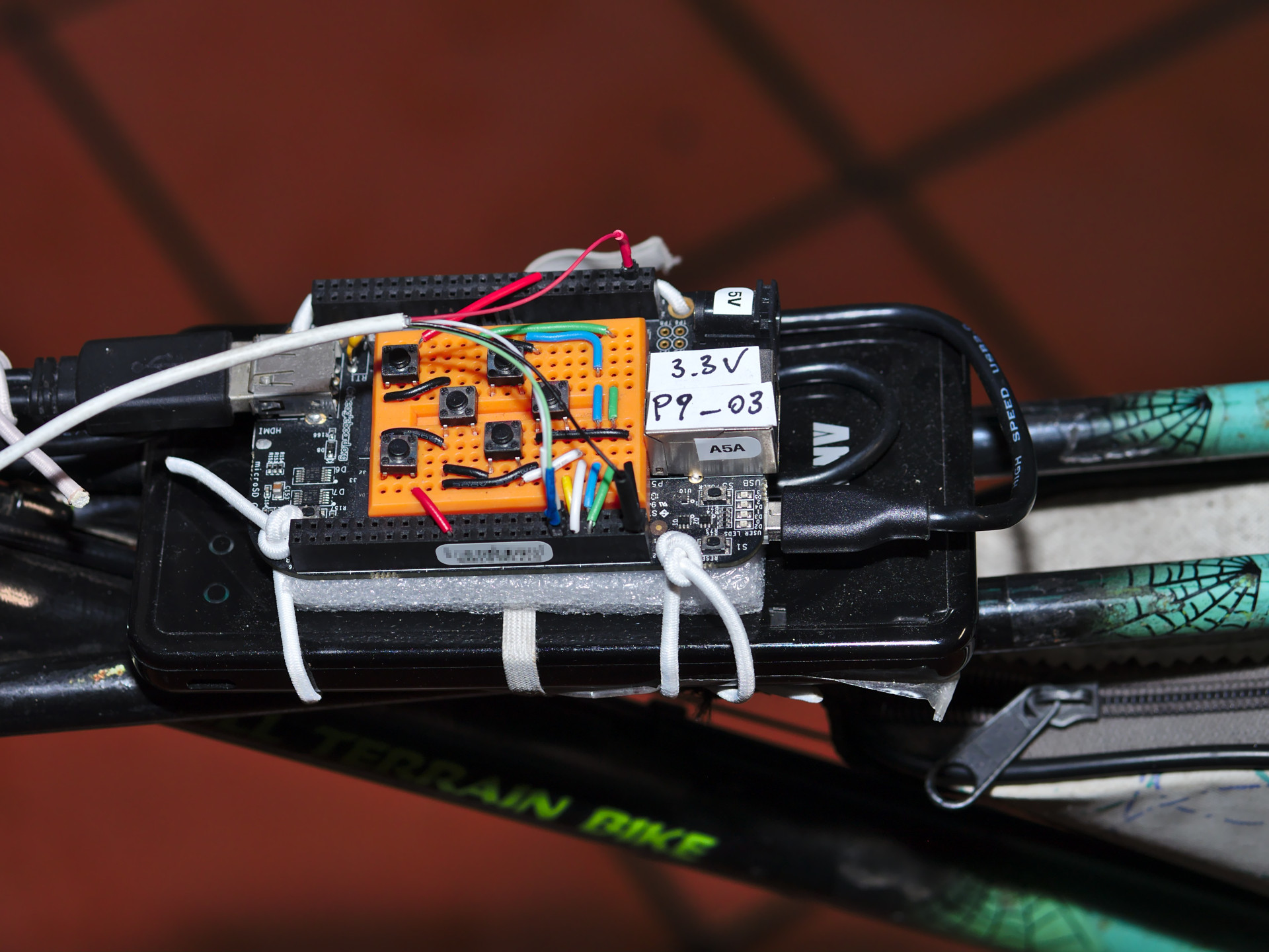
A keypad makes it possible to adjust some parameters to correct the keystone effect caused by the projection not being perpendicular to the ground:

Cyclabile - Keypad

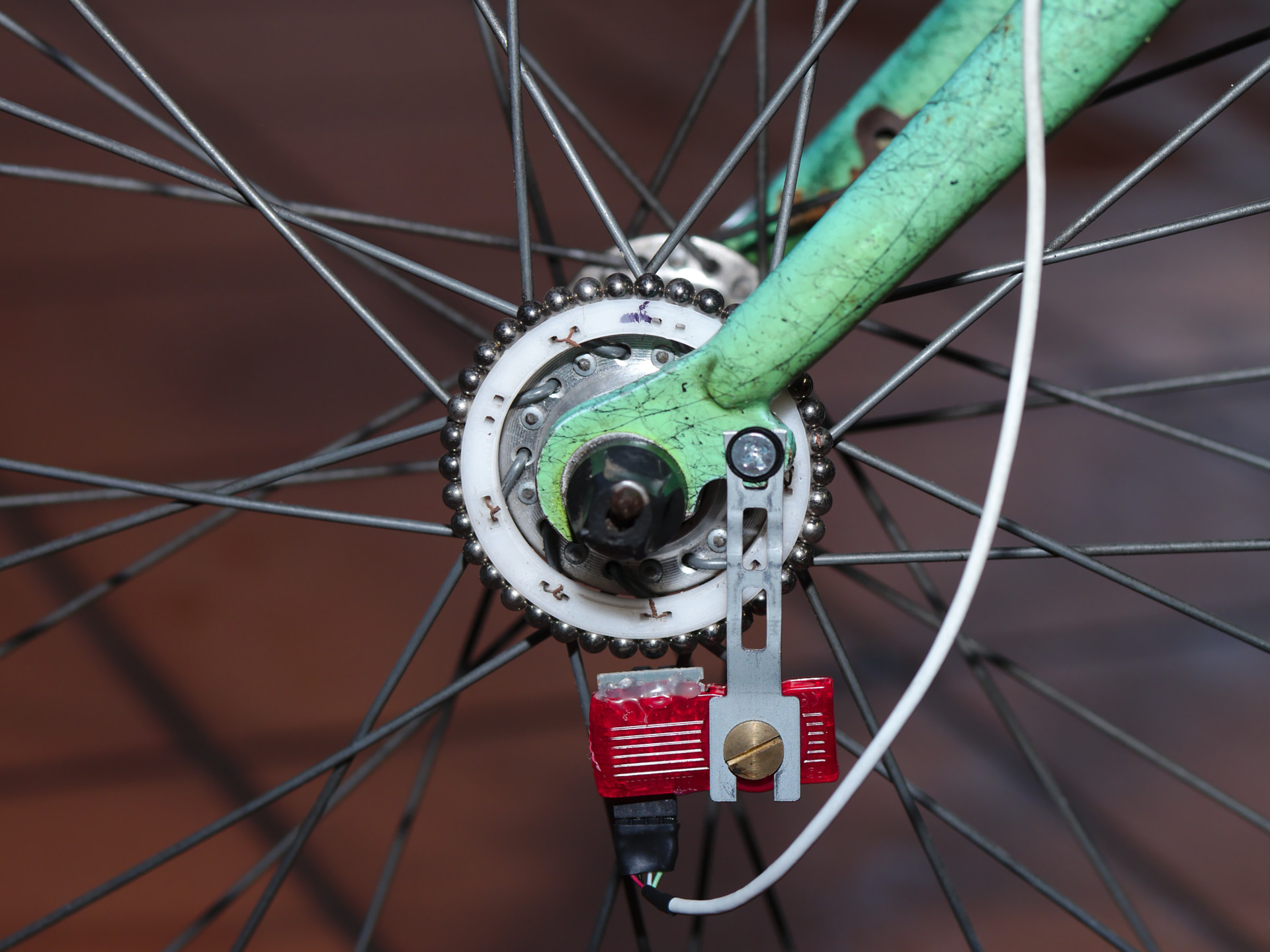
A reasonably precise rotary encoder, with a support to mount the magnets on the front wheel of the bike, detects movement at very low speeds.

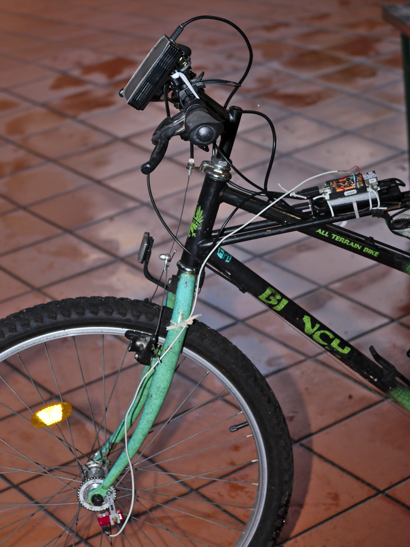
Cyclabile - Rotary EncoderHere are some more pictures of the build:

Cyclabile - Overview

Cyclabile - Demo

Similar projects

I am aware that there are similar projects around, but I guess what Cyclabile tries to accomplish is to make the scrolling of the projected image more realistic, to recreate the effect of a real bike lane.

Safety First

"Safety First" is an art installation by Vladimír Turner and Ondřej Mladý very much in the spirit of Cyclabile.

The difference is that Cyclabile is more portable and more interactive, the bike lane moves depending on the bike movement while "Safety First" used a video recording in a fixed loop.

Bike Projector Headlight

This is more generic, it's used to display info on the road, not specifically a bike lane.

Lightlane

A laser bike lane, it projects a static image.


Latest Images